Electronics Overview#
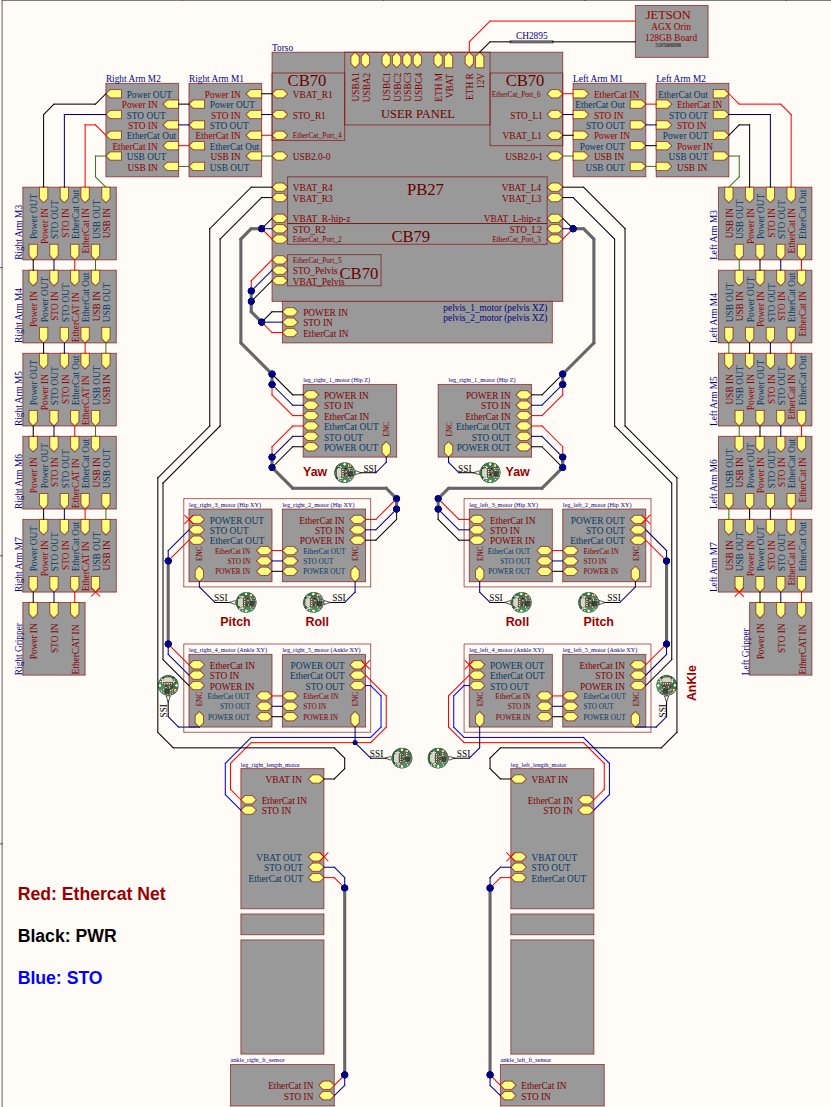
Fig. 9 Electrical overview of Kangaroo robot, describing power and communication topology.#
The diagram illustrates the full electrical architecture of Kangaroo, showing how all motor control boards are interconnected across the robot’s body. Three bus types are represented: the EtherCAT network (red), which connects all actuator slaves to the Control PC; the power distribution (black), which routes the main 63 V bus to every board; and the STO (Safe Torque Off) line (blue), which provides a hardware-level safety cut to all drives simultaneously. The EtherCAT network uses a star topology, with five independent chains branching from the torso in the following order: right leg, left leg, right arm, pelvis, and left arm. This arrangement mirrors the robot’s physical layout and allows each limb chain to be traced and diagnosed independently. In the case that the arms are not installed, the electrical overview diagram is still valid, the difference may be in the order of the salves ars the chains will be ordered: right leg, left leg, and pelvis.
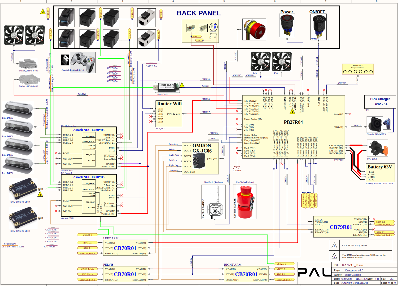
Fig. 10 Electrical overview of Kangaroo torso system, showing all the electrical components and their connection.#
This schematic details all electronic components housed inside the Kangaroo torso and their interconnections. The central power routing board (PR27B04) distributes battery power (63 V) to the motor control boards, the battery charger input, and the user panel connectors. An EtherCAT juntion (Omron GX-JC06) provides the EtherCAT star topology connections, with its port 1 connected to the PC where the EtherCAT master runs. A wireless router and swith provide internal LAN for control and multimedia PCs ad welll as wireless access point and WiFi client. The user panel exposes the main power switch, emergency stop button, and external connectors, while internal cooling fans manage thermal dissipation. The CB70R01 connection boards interface the torso and arm SEA actuators to the EtherCAT bus and power rails. This diagram is the primary reference for tracing signal and power paths during maintenance or troubleshooting of torso-mounted hardware.
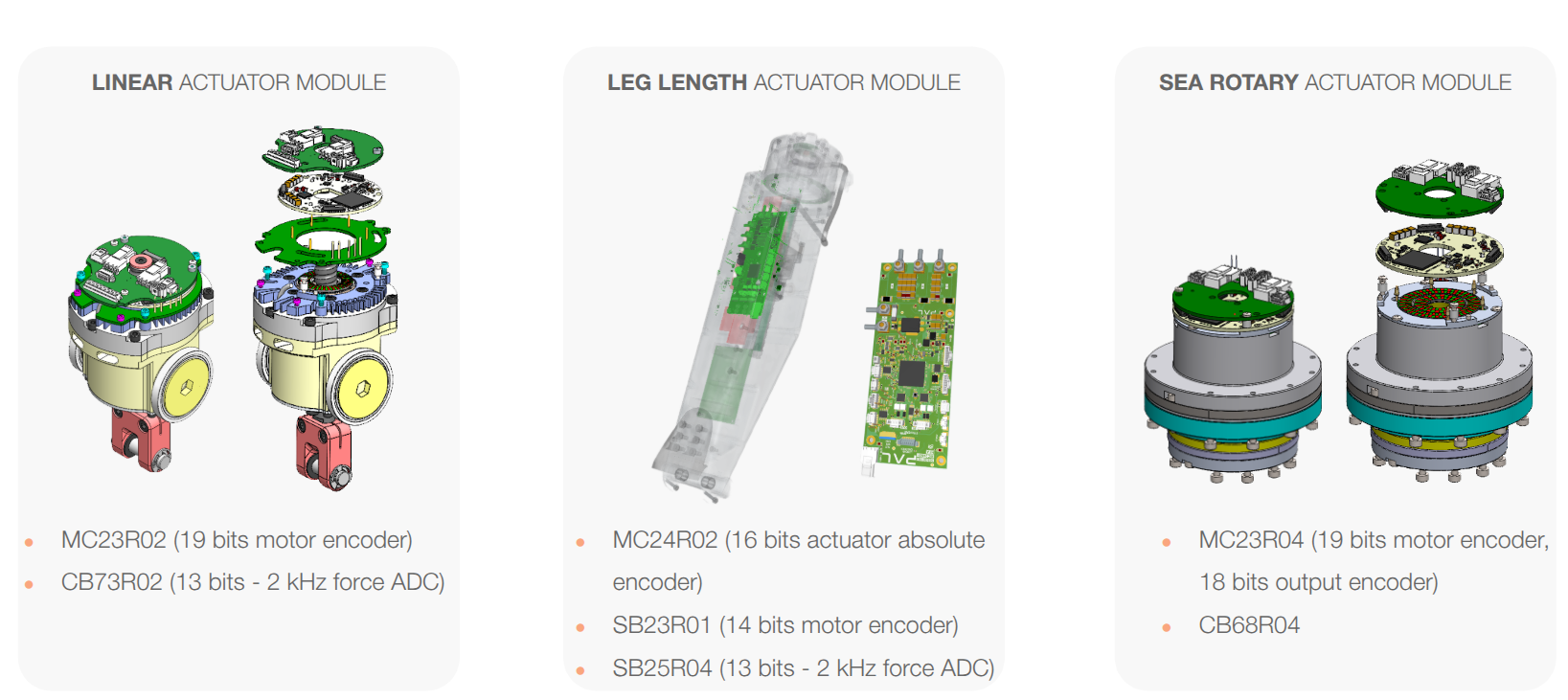
Fig. 11 Motor control boards used in Kangaroo.#
Kangaroo uses three distinct actuator module variants, each integrating motor drive electronics with the sensors required for its actuation type:
Linear Actuator Module — used for hip and ankle joints. Combines the MC23R02 motor drive (19-bit motor encoder) with the CB73R02 force sensing board (13-bit ADC at 2 kHz) for closed-loop force control on the linear actuator rod.
Leg Length Actuator Module — dedicated to the leg extension actuator. Features the MC24R02 drive with a 16-bit absolute actuator encoder for precise stroke measurement, plus the SB23R01 (14-bit motor encoder) and SB25R04 force ADC board.
SEA Rotary Actuator Module — used for pelvis and arm joints. The MC23R04 board integrates dual encoders (19-bit for the motor, 18-bit on the output after the elastic element) enabling torque estimation through deflection measurement, paired with the CB68R04 connection board.
EtherCAT and kinematic topology#
The EtherCAT topology is determined by the order of the slaves in the network which may change depending on the robot configurations (with or without arms, with or without FT sensors at the feet). The position 0 is the PC EtherCAT master, then the order of limbs connected to the network is right leg, left leg, pelvis, right arm and left arm.
| RT device motor name | EC Slave position — No feet FT | EC Slave position — With feet FT |
|---|---|---|
| Right leg chain | ||
| leg_right_1_motor | 1 | |
| leg_right_2_motor | 2 | |
| leg_right_3_motor | 3 | |
| leg_right_4_motor | 4 | |
| leg_right_5_motor | 5 | |
| leg_right_leg_length_motor | 6 | |
| ankle_ft_right | — | 7 (optional) |
| Left leg chain | ||
| leg_left_1_motor | 7 | 8 |
| leg_left_3_motor | 8 | 9 |
| leg_left_2_motor | 9 | 10 |
| leg_left_5_motor | 10 | 11 |
| leg_left_4_motor | 11 | 12 |
| leg_left_leg_length_motor | 12 | 13 |
| ankle_ft_left | — | 14 (optional) |
| Pelvis chain | ||
| pelvis_1_motor | 14 | 16 |
| pelvis_2_motor | 15 | 17 |
↑+1 — slave position = slave position of the row above in the same column, plus 1. Shaded cells (—) indicate the motor is not part of that configuration's EtherCAT chain.
| RT device motor name | EC Slave position — 4 DoF Arm | EC Slave position — 5 DoF Arm | EC Slave position — 7 DoF Arm |
|---|---|---|---|
| Right arm chain | |||
| arm_right_1_motor | pelvis_2_motor +1 | ||
| arm_right_2_motor | ↑+1 | ||
| arm_right_3_motor | ↑+1 | ||
| arm_right_4_motor | ↑+1 | ||
| arm_right_5_motor | — | ↑+1 | ↑+1 |
| arm_right_6_motor | — | — | ↑+1 |
| arm_right_7_motor | — | — | ↑+1 |
| wrist_ft_right | — | — | ↑+1 (optional) |
| gripper_right_finger_actuator | — | — | ↑+1 |
| Left arm chain | |||
| arm_left_1_motor | arm_right_4_motor +1 | arm_right_5_motor +1 | gripper_right_finger_actuator +1 |
| arm_left_2_motor | ↑+1 | ||
| arm_left_3_motor | ↑+1 | ||
| arm_left_4_motor | ↑+1 | ||
| arm_left_5_motor | — | ↑+1 | ↑+1 |
| arm_left_6_motor | — | — | ↑+1 |
| arm_left_7_motor | — | — | ↑+1 |
| wrist_ft_left | — | — | ↑+1 (optional) |
| gripper_left_finger_actuator | — | — | ↑+1 |