Robot Design#
Kangaroo is a bipedal humanoid robot designed and developed by PAL Robotics. It features unique characteristics in mechatronics, kinematics, and dynamics. Kangaroo’s legs actuation system relies on linear actuators located near the pelvis area, with motion transmitted to the joints through a complex system of hybrid serial-parallel linkages. The placement of all the leg actuators near the base of the robot reduces equivalent Cartesian inertia at the feet and centroidal angular momentum. The custom linear actuators with integrated force sensors provide a large range of motion as well as high speed and torques at the legs’ joints. The custom rotary actuators with integrated Series Elastic Element provide compact and robust modules used in the upper body for the pelvis and arms joints.
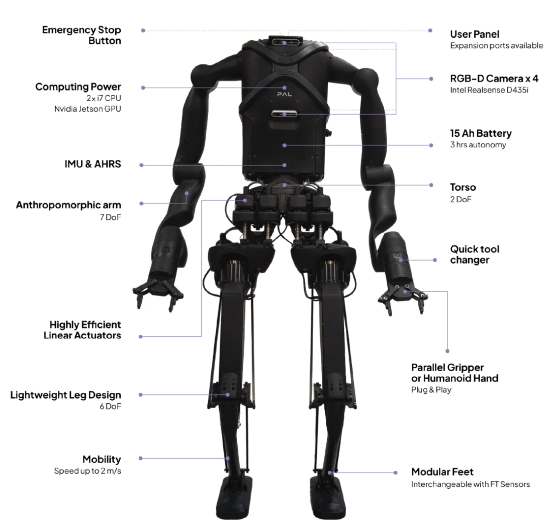
Fig. 2 Kangaroo with 7 DoF arms and components description.#
Kinematics#
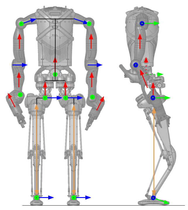
Fig. 3 Kangaroo kinematics at joint level for the 7 DoF arm configuration.#
Lower body#
The Kangaroo lower body has 12 active Degrees of Freedom (DoF), 6 per leg, plus a 2 DoF torso (Roll and Yaw).
The hip yaw is actuated by a linear actuator with crank slider mechanism.
Hip pitch and roll joints are obtained with 2 linear actuators in a differential configuration.
The leg length is controlled by a single linear actuator placed inside the femur and a combination of 3 closed bar linkage systems. The result is a vertical motion of the foot with respect to the hip when the leg length actuator is activated.
The ankle actuators are located in the back of each femur and 2 four bar linkages on each side of the leg transmit the motion to the foot, to obtain pitch and roll motion.
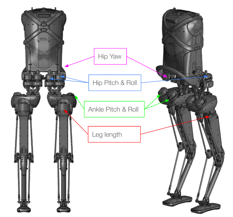
Fig. 4 Actuators placement in Kangaroo lower body.#
Upper body#
The upper body can have different configurations, depending on the number of degrees of freedom of the armas and the type of end effectors: no arms, 4 DoF arms, 5 DoF arms and 7 DoF arms are available. The 7 DoF arm design has a payload of 3.5 kg when fully extended but the maximum continuous payload is larger inside the workspace. Series Elastic Actuators (SEAs) are used with 3 different sizes S+, S- and XS.
Materials#
The robot structure uses a combination of materials selected for stiffness, weight, and impact resistance:
Aluminum alloy — actuator housings, bar linkages, and structural parts
Steel — small shafts that carry high loads
Carbon fiber — tibia tube
Rigid plastic — covers
Flexible plastic — feet sole and torso (impact absorption)
Joint Specifications#
Joint |
Min pos |
Max pos |
Max speed |
Max torque/force |
|---|---|---|---|---|
Hip Yaw |
−15° |
45° |
8 rad/s |
80 Nm |
Hip Roll |
−25° |
+25° |
9 rad/s |
130 Nm |
Hip Pitch |
−40° |
+42.5° |
6 rad/s |
230 Nm |
Leg Length |
0.132 m |
0.715 m |
3 m/s |
1 kN |
Ankle Pitch |
−42.5° |
42.5° |
9 rad/s |
140 Nm |
Ankle Roll |
−25° |
25° |
15 rad/s |
80 Nm |
Pelvis Roll |
-20° |
20° |
3.14 rad/s |
100 Nm |
Pelvis Yaw |
-75° |
75° |
2.24 rad/s |
140 Nm |
Arm 1 Y |
-150° |
150° |
3.14 rad/s |
70 Nm |
Arm 2 X |
-60° |
140° |
3.14 rad/s |
70 Nm |
Arm 3 Z |
-150° |
150° |
6.28 rad/s |
45 Nm |
Arm 4 Y |
-60° |
140° |
6.28 rad/s |
45 Nm |
Arm 5 Z |
-150° |
150° |
6.28 rad/s |
45 Nm |
Arm 6 Y |
-100° |
170° |
6.28 rad/s |
30 Nm |
Arm 7 Z |
-150° |
150° |
6.28 rad/s |
30 Nm |
Modular Foot#
The ankle features a modular mechanical interface that allows the foot to be easily replaced. Two variants are available: a simple foot and a sensorized foot equipped with a 6-axis Force/Torque sensor.
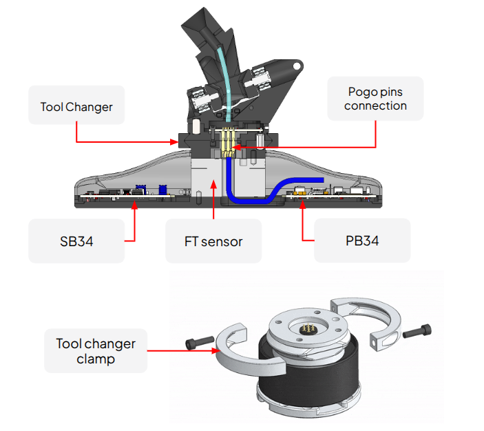
Fig. 5 Kangaroo modular foot.#
The mechanical size and weight of the 2 type of feet is the same, meaning that the robot kinematic and dynamic model doesn´t change when the foot is changed.
Electrical and Mechanical Interface#
The foot attaches to the ankle via a Heavy Duty Tool Changer — a quick-release locking ring mechanism that provides a rigid, repeatable connection. Electrical signals pass through the interface via a Pogo pin connector embedded in the mating face, eliminating exposed cables at the joint.
Internally, all cabling is routed through the center of the XY rotation axes of the ankle, so the cable bundle does not flex or bind as the ankle moves in pitch and roll.
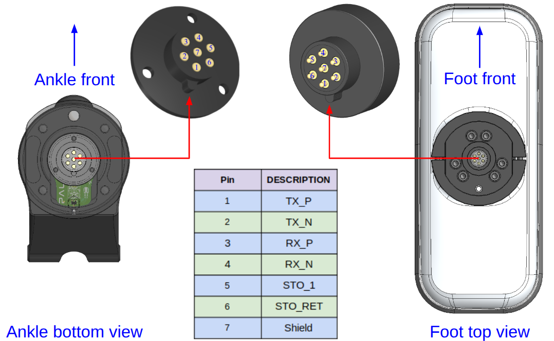
Fig. 6 Kangaroo electrical interface between ankle and FT foot with pogo pins for EtherCAT and power.#
The sensorized foot houses 2 boards:
PB34 — power board
SB34 — sensor interface board (ADC and EtherCAT) These boards condition and transmit the FT sensor data to the Control PC over the robot’s internal EtherCAT bus.
On the ankle flange the CB87 connection board integrates pogo pins and efuse to manage the activation or deactivation of power upon connection and disconnection of the foot. The CB87 also control a LED which is visible on the back of the ankle tool flange which has the following coloring statuses:
| LED Color | Status |
|---|---|
| RED | Fault or error detected |
| White | All systems are operational |
| Blue | Foot tool changer is in closed position |
| Purple | -------------------- |
| Yellow | No connection or attachement detected |
Changing the Foot#
Power off the robot
Unlock the tool changer clamping ring at the ankle, by removing the 2 M5 screws.
Pull the foot module straight down to detach — the pogo pins disengage automatically.
Align the replacement foot module with the mating face and push until the tool changer locks.
Lock again the tool changer clamping ring at the ankle with the 2 M5 screws.
Power on the robot
No re-cabling or re-configuration is required when swapping between the simple and sensorized variants; the electronics board in the foot detects sensor presence automatically and power it. Software reconfiguration is at startup is automatic, the sensors shall be detected and the control stack automatically load the driver and start the components in ros2_control. Additional details are available at robot reflection system