# Controllers Overview
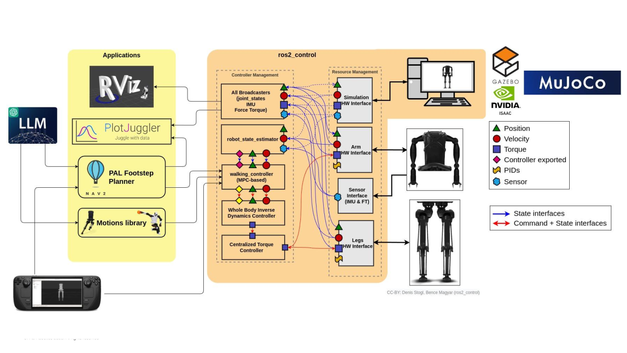
Kangaroo uses [ros2_control](https://control.ros.org/master/index.html) as its hardware abstraction and controller management framework. This page explains the architecture and how it is applied to Kangaroo, before diving into the individual controllers documented in this section.
## ros2_control Architecture
ros2_control separates robot software into three layers that communicate through a shared in-memory data bus called the **hardware resource interface**:
```
┌─────────────────────────────────────────────────────┐
│ Controller Manager │
│ loads, starts, stops, and switches controllers │
└───────────────┬─────────────────────────────────────┘
│ command / state interfaces
┌───────────────▼─────────────────────────────────────┐
│ Resource Manager │
│ owns the hardware interface data bus │
└───────────────┬─────────────────────────────────────┘
│ read() / write()
┌───────────────▼─────────────────────────────────────┐
│ Hardware Interface Plugin │
│ talks to the actual hardware or simulator │
└─────────────────────────────────────────────────────┘
```
 ### Key Components
#### Controller Manager
The `controller_manager` node is the central orchestrator. It loads controller plugins at runtime, manages their lifecycle (`configure` → `activate` → `deactivate` → `cleanup`), and enforces that only one controller claims each hardware interface at any given time.
#### Hardware Interface
The hardware interface plugin implements the `read()` / `write()` cycle that bridges the ros2_control data bus to the real actuators (or simulator). Kangaroo's hardware interface handles the EtherCAT communication to the actuator drives and exposes interfaces for two distinct component types: **joints** (joint-space values, after the transmission) and **actuators** (motor-side values, before the transmission).
**Joint interfaces**: joint-space quantities, transmission applied:
| Interface type | Direction | Description |
|---|---|---|
| `position` | state | Current joint angle (rad) |
| `absolute_position` | state | joint angle projected from the absolute encoder (rad) |
| `velocity` | state | Current joint velocity (rad/s) |
| `effort` | state | Current joint torque (Nm) |
| `position` | command | Desired joint angle |
| `velocity` | command | Desired joint velocity |
| `effort` | command | Desired joint torque |
**Actuator interfaces**: motor-side quantities, transmission bypassed:
| Interface type | Direction | Description |
|---|---|---|
| `position` | state | Current actuator position (m) |
| `absolute_position` | state | Actuator position from the absolute encoder (m) |
| `velocity` | state | Current actuator velocity (m/s) |
| `effort` | state | Current actuator force (N) |
| `current` | state | Actual motor phase current (A) |
| `force` | state | Force from the internal load cell (N) |
| `position` | command | Desired actuator position (m) |
| `velocity` | command | Desired actuator velocity (m/s) |
| `effort` | command | Desired actuator force (N) |
| `current` | command | Desired motor current (A) |
#### Controllers and Broadcasters
Controllers are plugins that read information from the state interfaces and then write the commands to the command interfaces. They run in the same real-time control loop as the hardware interface. Multiple controllers can be active simultaneously as long as they claim disjoint sets of command interfaces. For example, `joint_trajectory_controller`, `actuator_pid_controllers`, `forward_command_controller`, `pid_controllers` etc.
Broadcasters are the set of controller plugins that only claim a set of state interfaces and use the information to manipulate and publish the information. For example, `joint_state_broadcaster`, `imu_sensor_broadcaster`, `force_torque_sensor_broadcaster`.
## How ros2_control is Used in Kangaroo
At startup the following sequence takes place:
1. The **hardware interface** plugins connects to the actuator drives over EtherCAT and initialises all the sensors and actuators.
2. The **`pid_command_controller`** runs once to upload the per-actuator PID gains for every control mode (position, velocity, current): see [Actuator PID Controller](actuator_pid.md).
3. The **Controller Manager** loads the set of controllers/broadcasters dynamically launched via different pal modules.
4. The operator (or launch file) activates the appropriate controller for the current task.
Controllers can be switched at runtime without restarting the robot using the Controller Manager service API or the `ros2 control` CLI:
```bash
# List all loaded controllers and their state
ros2 control list_controllers
# Switch active controllers
ros2 control switch_controllers \
--activate \
--deactivate
```
## Different Interfaces on the Robot
Kangaroo exposes hardware interfaces through the ros2_control resource manager. Each interface is addressed as `/`. There are two categories: **command interfaces** (written by controllers to drive actuators) and **state interfaces** (read-only feedback from sensors and actuators).
Use `ros2 control list_hardware_interfaces` on the robot to see the live status of every interface.
The lower-body hardware is organized into the following components:
| Component pattern | Count | Description |
|---|---|---|
| `leg_left_N_actuator` / `leg_right_N_actuator` | 6 per side | Leg linear actuators (N = 1–5, length), covering hip yaw, hip roll, hip pitch, ankle pitch, ankle roll, and leg length |
| `leg_left_N_joint` / `leg_right_N_joint` | 6 per side | Joint-space view of the same leg linear actuators (after transmission) |
| `leg_left_femur_joint` / `leg_right_femur_joint` | 1 per side | Derived femur joint position from the parallel linkage mechanism (state only) |
| `leg_left_knee_joint` / `leg_right_knee_joint` | 1 per side | Derived knee joint position from the parallel linkage mechanism (state only) |
| `pelvis_1_actuator` / `pelvis_2_actuator` | 2 | Pelvis roll and pitch actuators |
| `pelvis_1_joint` / `pelvis_2_joint` | 2 | Joint-space view of the pelvis actuators |
| `torso_imu_sensor` | 1 | IMU mounted on the torso |
| `robot/is_safe` | 1 | Global safety flag |
The `_actuator` interfaces expose raw motor-side quantities (current, internal force sensor, PID gains applied on the drive), while the `_joint` interfaces expose the corresponding joint-space values after the gearbox and transmission.
### Command Interfaces
Command interfaces are claimed exclusively by an active controller. An interface marked `[claimed]` is in use; `[unclaimed]` is available.
**Per leg linear actuators** (`leg_{left|right}_{1-5|length}_actuator`):
| Interface | Description |
|---|---|
| `position` | Target actuator position (m) |
| `velocity` | Target actuator velocity (m/s) |
| `effort` | Target actuator effort (N) |
| `current` | Target motor current (A) |
| `force` | Target force from the internal force sensor loop (N) |
| `mode` | Control mode selector (position / velocity / current / force) |
| `position_offset` | Additive offset applied on top of the position command |
| `force_offset` | Additive offset applied on top of the force command |
| `position.proportional` | P gain for the on-drive position PID |
| `position.integral` | I gain for the on-drive position PID |
| `position.derivative` | D gain for the on-drive position PID |
| `position.feedforward` | Feedforward term for the on-drive position PID |
| `velocity.proportional` | P gain for the on-drive velocity PID |
| `velocity.integral` | I gain for the on-drive velocity PID |
| `velocity.derivative` | D gain for the on-drive velocity PID |
| `velocity.feedforward` | Feedforward term for the on-drive velocity PID |
| `current.proportional` | P gain for the on-drive current PID |
| `current.integral` | I gain for the on-drive current PID |
| `current.derivative` | D gain for the on-drive current PID |
| `current.feedforward` | Feedforward term for the on-drive current PID |
| `force.proportional` | P gain for the on-drive force PID |
| `force.integral` | I gain for the on-drive force PID |
| `force.derivative` | D gain for the on-drive force PID |
| `force.feedforward` | Feedforward term for the on-drive force PID |
| `input.0` | Raw encoder input channel (present but not used) |
| `impedance.stiffness` | Stiffness gain for impedance control |
| `impedance.damping` | Damping gain for impedance control |
**Per leg joint** (`leg_{left|right}_{1-5|length}_joint`):
| Interface | Description |
|---|---|
| `position` | Target joint position (rad or m) |
| `velocity` | Target joint velocity (rad/s or m/s) |
| `effort` | Target joint effort (Nm or N) |
| `torque`/`force` | Target joint torque/force (Nm or N) |
**Pelvis actuators** (`pelvis_{1|2}_actuator`) expose the same interface set as leg actuators. The corresponding `pelvis_{1|2}_joint` expose `position`, `velocity`, and `effort`.
**Safety interface:**
| Interface | Description |
|---|---|
| `robot/is_safe` | Boolean flag (`true` = safe, `false` = fault); controllers can write `false` to signal an unsafe condition to the hardware interface |
### State Interfaces
State interfaces are read-only and can be claimed by any number of controllers/broadcasters simultaneously.
**Per leg rotary actuator and leg-length actuator** (`leg_{left|right}_{1-5|length}_actuator`):
| Interface | Description |
|---|---|
| `position` | Current actuator position (rad or m) |
| `absolute_position` | Crank/joint position referenced to the absolute encoder (rad or m) |
| `velocity` | Current actuator velocity (rad/s or m/s) |
| `effort` | Current actuator effort/torque (Nm or N) |
| `current` | Actual motor phase current (A) |
| `force` | Force measured by the internal load cell / force sensor (N) |
| `force_offset` | Current force offset applied by the drive (N) |
| `mode` | Active control mode reported by the drive |
| `position_offset` | Active position offset reported by the drive |
| `temperature_board` | Drive electronics board temperature (°C) |
| `temperature_motor` | Motor winding temperature (°C) |
| `position.proportional` / `position.integral` / `position.derivative` / `position.feedforward` | Active position PID gains echoed back from the drive |
| `velocity.proportional` / `velocity.integral` / `velocity.derivative` / `velocity.feedforward` | Active velocity PID gains echoed back from the drive |
| `current.proportional` / `current.integral` / `current.derivative` / `current.feedforward` | Active current PID gains echoed back from the drive |
| `force.proportional` / `force.integral` / `force.derivative` / `force.feedforward` | Active force PID gains echoed back from the drive |
| `input.0` | Raw encoder input channel (present but not used) |
| `impedance.stiffness` | Stiffness gain for impedance control echoed back from the drive |
| `impedance.damping` | Damping gain for impedance control echoed back from the drive |
**Per leg joint** (`leg_{left|right}_{1-5|length}_joint`):
| Interface | Description |
|---|---|
| `position` | Current joint position (rad or m) |
| `absolute_position` | Joint position from the absolute encoder perspective (rad or m) |
| `velocity` | Current joint velocity (rad/s or m/s) |
| `effort` | Current joint effort (Nm or N) |
**Derived parallel-linkage joints** (state only: no command interfaces):
| Interface | Description |
|---|---|
| `leg_{left\|right}_femur_joint/position` | Femur joint angle computed from the parallel four-bar linkage (rad) |
| `leg_{left\|right}_femur_joint/velocity` | Femur joint velocity (rad/s) |
| `leg_{left\|right}_femur_joint/effort` | Femur joint effort (Nm) |
| `leg_{left\|right}_knee_joint/position` | Knee joint angle computed from the parallel four-bar linkage (rad) |
| `leg_{left\|right}_knee_joint/velocity` | Knee joint velocity (rad/s) |
| `leg_{left\|right}_knee_joint/effort` | Knee joint effort (Nm) |
**Pelvis actuators and joints** follow the same state interface layout as leg actuators and joints respectively.
**IMU sensor** (`torso_imu_sensor`):
| Interface | Description |
|---|---|
| `orientation.x` / `.y` / `.z` / `.w` | Torso orientation as a quaternion |
| `angular_velocity.x` / `.y` / `.z` | Angular velocity in the torso frame (rad/s) |
| `linear_acceleration.x` / `.y` / `.z` | Linear acceleration in the torso frame (m/s²) |
**Safety interface:**
| Interface | Description |
|---|---|
| `robot/is_safe` | Boolean flag reporting the current safety status (`true` = safe, `false` = fault) |
## Transmissions
Transmissions play a crucial role in robotics by converting motion and force between actuators and joints. In Kangaroo, custom transmissions are implemented to handle complex kinematic relationships, particularly for leg mechanisms. They map the motion from the high-speed, low-torque actuators to the desired joint movements, often involving mechanical linkages that provide mechanical advantage or convert linear motion to rotary motion, or vice-versa.
The transmissions map the following interfaces between the actuator space and the joint space:
| Interface | Direction | Description |
|---|---|---|
| `position` | Bidirectional | Maps actuator position (m) to joint position (rad) and vice-versa |
| `velocity` | Bidirectional | Maps actuator velocity (m/s) to joint velocity (rad/s) and vice-versa |
| `effort` | Bidirectional | Maps actuator force (N) to joint torque (Nm) and vice-versa |
| `force` | Bidirectional | Maps actuator force sensor readings (N) to joint torque (Nm) and vice-versa |
| `absolute_position` | Actuator → Joint | Maps absolute encoder position from actuator to joint |
Some transmissions, such as `HipXYTransmission` and `AnkleXYTransmission`, are **differential transmissions**: they combine the motion of two actuators to produce two output joint motions, and vice-versa. Among these, the `AnkleXYTransmission` is the most complex, as it additionally incorporates the states of the femur and knee derived from the parallel linkage to solve the forward kinematics of the ankle mechanism.
| Transmission Type | Actuators Involved | Corresponding Joints (Commandable) | Read-only/Derived Components |
|---|---|---|---|
| HipZTransmission | Hip Actuator 1 | Hip Yaw (Jont 1) | - |
| HipXYTransmission | Hip Actuator 2, Hip Actuator 3 | Hip Pitch (Joint 2), Hip Roll (Joint 3)| - |
| LegLengthTransmission | Leg Length Actuator | Leg Length | - |
| LegLengthStateTransmission | Leg Length Actuator | - | Femur, Knee |
| AnkleXYTransmission | Ankle Actuator 4, Ankle Actuator 5, Leg Length Actuator(read-only) | Ankle Pitch (Joint 4) , Ankle Roll (Joint 5) | - |
### Claiming Command Interfaces: Rules and Restrictions
Command interfaces for a given joint or actuator are **mutually exclusive**: only one control type can be active at a time. For instance, if `leg_left_1_actuator` is already commanded via its `position` interface, attempting to additionally claim `velocity` or `effort` will fail. The same rule applies to joint interfaces.
- A joint interface and its corresponding actuator interface cannot be claimed simultaneously, nor can one be claimed while the other is already active. This restriction applies only to the `position`, `velocity`, `effort`, and `force`/`torque` interfaces, not to gain interfaces.
- Joints and actuators that share a transmission must be claimed together. Claiming only one side of a transmission pair will cause the controller switch to fail.
The diagram below illustrates how the command path differs depending on which interface type is claimed:
```
Joint interface: Joint Command ──► Transmission ──► Actuator (hardware)
Actuator interface: Actuator Command ──────────────────► Actuator (hardware)
(transmission skipped)
```
When a **joint interface** is claimed, the command passes through the transmission layer, which maps joint-space values to actuator-space values. When an **actuator interface** is claimed directly, the transmission is bypassed entirely and the command is sent straight to the hardware.
The table below shows which actuator control mode is activated based on the combination of command interfaces claimed:
| Claimed interface(s) | Actuator control mode | Notes |
|---|---|---|
| `position` | Position | `rad` for rotary joints converted to `m` for linear actuators |
| `velocity` | Velocity | `rad/sec` for rotary joints converted to `m/sec` for linear actuators |
| `effort` | Current | Nm (joint) / N (actuator) converted to A |
| `current` | Current | Direct current command in A |
| `force` | Force | Force-loop on internal force sensor |
| `torque` | Force | Nm converted to N via transmission |
| `position` + `velocity` | Impedance (current) | Stiffness/damping control, output in current |
| `position` + `velocity` + `impedance_force.feed_forward` | Impedance (force) | Impedance with feed-forward force term |
## Available Controllers
The table below summarises every controller available on Kangaroo and its primary use case.
| Controller | Use Case |
|---|---|
| [Joint Trajectory Controller](joint_trajectory.md) | Execute pre-planned joint trajectories (MoveIt, playback) |
| [PlayMotion](play_motion2.md) | Replay named motions stored in the parameter server |
| [Whole Body Controller (WBC)](wbc.md) | Hierarchical task-space control with joint-limit awareness |
| [Actuator PID Controller](actuator_pid.md) | Upload per-actuator PID gains at startup |
| [Torque Controller](torque.md) | Direct joint torque / effort commanding |
| [Gravity Compensation](gravity_compensation.md) | Compensate for gravity to allow compliant backdrivable operation |
| [Force Reconstruction (Wrench Estimator)](force_estimation.md) | Reconstruct the external foot wrench from actuator forces via the full model, no FT sensor required |
### Key Components
#### Controller Manager
The `controller_manager` node is the central orchestrator. It loads controller plugins at runtime, manages their lifecycle (`configure` → `activate` → `deactivate` → `cleanup`), and enforces that only one controller claims each hardware interface at any given time.
#### Hardware Interface
The hardware interface plugin implements the `read()` / `write()` cycle that bridges the ros2_control data bus to the real actuators (or simulator). Kangaroo's hardware interface handles the EtherCAT communication to the actuator drives and exposes interfaces for two distinct component types: **joints** (joint-space values, after the transmission) and **actuators** (motor-side values, before the transmission).
**Joint interfaces**: joint-space quantities, transmission applied:
| Interface type | Direction | Description |
|---|---|---|
| `position` | state | Current joint angle (rad) |
| `absolute_position` | state | joint angle projected from the absolute encoder (rad) |
| `velocity` | state | Current joint velocity (rad/s) |
| `effort` | state | Current joint torque (Nm) |
| `position` | command | Desired joint angle |
| `velocity` | command | Desired joint velocity |
| `effort` | command | Desired joint torque |
**Actuator interfaces**: motor-side quantities, transmission bypassed:
| Interface type | Direction | Description |
|---|---|---|
| `position` | state | Current actuator position (m) |
| `absolute_position` | state | Actuator position from the absolute encoder (m) |
| `velocity` | state | Current actuator velocity (m/s) |
| `effort` | state | Current actuator force (N) |
| `current` | state | Actual motor phase current (A) |
| `force` | state | Force from the internal load cell (N) |
| `position` | command | Desired actuator position (m) |
| `velocity` | command | Desired actuator velocity (m/s) |
| `effort` | command | Desired actuator force (N) |
| `current` | command | Desired motor current (A) |
#### Controllers and Broadcasters
Controllers are plugins that read information from the state interfaces and then write the commands to the command interfaces. They run in the same real-time control loop as the hardware interface. Multiple controllers can be active simultaneously as long as they claim disjoint sets of command interfaces. For example, `joint_trajectory_controller`, `actuator_pid_controllers`, `forward_command_controller`, `pid_controllers` etc.
Broadcasters are the set of controller plugins that only claim a set of state interfaces and use the information to manipulate and publish the information. For example, `joint_state_broadcaster`, `imu_sensor_broadcaster`, `force_torque_sensor_broadcaster`.
## How ros2_control is Used in Kangaroo
At startup the following sequence takes place:
1. The **hardware interface** plugins connects to the actuator drives over EtherCAT and initialises all the sensors and actuators.
2. The **`pid_command_controller`** runs once to upload the per-actuator PID gains for every control mode (position, velocity, current): see [Actuator PID Controller](actuator_pid.md).
3. The **Controller Manager** loads the set of controllers/broadcasters dynamically launched via different pal modules.
4. The operator (or launch file) activates the appropriate controller for the current task.
Controllers can be switched at runtime without restarting the robot using the Controller Manager service API or the `ros2 control` CLI:
```bash
# List all loaded controllers and their state
ros2 control list_controllers
# Switch active controllers
ros2 control switch_controllers \
--activate \
--deactivate
```
## Different Interfaces on the Robot
Kangaroo exposes hardware interfaces through the ros2_control resource manager. Each interface is addressed as `/`. There are two categories: **command interfaces** (written by controllers to drive actuators) and **state interfaces** (read-only feedback from sensors and actuators).
Use `ros2 control list_hardware_interfaces` on the robot to see the live status of every interface.
The lower-body hardware is organized into the following components:
| Component pattern | Count | Description |
|---|---|---|
| `leg_left_N_actuator` / `leg_right_N_actuator` | 6 per side | Leg linear actuators (N = 1–5, length), covering hip yaw, hip roll, hip pitch, ankle pitch, ankle roll, and leg length |
| `leg_left_N_joint` / `leg_right_N_joint` | 6 per side | Joint-space view of the same leg linear actuators (after transmission) |
| `leg_left_femur_joint` / `leg_right_femur_joint` | 1 per side | Derived femur joint position from the parallel linkage mechanism (state only) |
| `leg_left_knee_joint` / `leg_right_knee_joint` | 1 per side | Derived knee joint position from the parallel linkage mechanism (state only) |
| `pelvis_1_actuator` / `pelvis_2_actuator` | 2 | Pelvis roll and pitch actuators |
| `pelvis_1_joint` / `pelvis_2_joint` | 2 | Joint-space view of the pelvis actuators |
| `torso_imu_sensor` | 1 | IMU mounted on the torso |
| `robot/is_safe` | 1 | Global safety flag |
The `_actuator` interfaces expose raw motor-side quantities (current, internal force sensor, PID gains applied on the drive), while the `_joint` interfaces expose the corresponding joint-space values after the gearbox and transmission.
### Command Interfaces
Command interfaces are claimed exclusively by an active controller. An interface marked `[claimed]` is in use; `[unclaimed]` is available.
**Per leg linear actuators** (`leg_{left|right}_{1-5|length}_actuator`):
| Interface | Description |
|---|---|
| `position` | Target actuator position (m) |
| `velocity` | Target actuator velocity (m/s) |
| `effort` | Target actuator effort (N) |
| `current` | Target motor current (A) |
| `force` | Target force from the internal force sensor loop (N) |
| `mode` | Control mode selector (position / velocity / current / force) |
| `position_offset` | Additive offset applied on top of the position command |
| `force_offset` | Additive offset applied on top of the force command |
| `position.proportional` | P gain for the on-drive position PID |
| `position.integral` | I gain for the on-drive position PID |
| `position.derivative` | D gain for the on-drive position PID |
| `position.feedforward` | Feedforward term for the on-drive position PID |
| `velocity.proportional` | P gain for the on-drive velocity PID |
| `velocity.integral` | I gain for the on-drive velocity PID |
| `velocity.derivative` | D gain for the on-drive velocity PID |
| `velocity.feedforward` | Feedforward term for the on-drive velocity PID |
| `current.proportional` | P gain for the on-drive current PID |
| `current.integral` | I gain for the on-drive current PID |
| `current.derivative` | D gain for the on-drive current PID |
| `current.feedforward` | Feedforward term for the on-drive current PID |
| `force.proportional` | P gain for the on-drive force PID |
| `force.integral` | I gain for the on-drive force PID |
| `force.derivative` | D gain for the on-drive force PID |
| `force.feedforward` | Feedforward term for the on-drive force PID |
| `input.0` | Raw encoder input channel (present but not used) |
| `impedance.stiffness` | Stiffness gain for impedance control |
| `impedance.damping` | Damping gain for impedance control |
**Per leg joint** (`leg_{left|right}_{1-5|length}_joint`):
| Interface | Description |
|---|---|
| `position` | Target joint position (rad or m) |
| `velocity` | Target joint velocity (rad/s or m/s) |
| `effort` | Target joint effort (Nm or N) |
| `torque`/`force` | Target joint torque/force (Nm or N) |
**Pelvis actuators** (`pelvis_{1|2}_actuator`) expose the same interface set as leg actuators. The corresponding `pelvis_{1|2}_joint` expose `position`, `velocity`, and `effort`.
**Safety interface:**
| Interface | Description |
|---|---|
| `robot/is_safe` | Boolean flag (`true` = safe, `false` = fault); controllers can write `false` to signal an unsafe condition to the hardware interface |
### State Interfaces
State interfaces are read-only and can be claimed by any number of controllers/broadcasters simultaneously.
**Per leg rotary actuator and leg-length actuator** (`leg_{left|right}_{1-5|length}_actuator`):
| Interface | Description |
|---|---|
| `position` | Current actuator position (rad or m) |
| `absolute_position` | Crank/joint position referenced to the absolute encoder (rad or m) |
| `velocity` | Current actuator velocity (rad/s or m/s) |
| `effort` | Current actuator effort/torque (Nm or N) |
| `current` | Actual motor phase current (A) |
| `force` | Force measured by the internal load cell / force sensor (N) |
| `force_offset` | Current force offset applied by the drive (N) |
| `mode` | Active control mode reported by the drive |
| `position_offset` | Active position offset reported by the drive |
| `temperature_board` | Drive electronics board temperature (°C) |
| `temperature_motor` | Motor winding temperature (°C) |
| `position.proportional` / `position.integral` / `position.derivative` / `position.feedforward` | Active position PID gains echoed back from the drive |
| `velocity.proportional` / `velocity.integral` / `velocity.derivative` / `velocity.feedforward` | Active velocity PID gains echoed back from the drive |
| `current.proportional` / `current.integral` / `current.derivative` / `current.feedforward` | Active current PID gains echoed back from the drive |
| `force.proportional` / `force.integral` / `force.derivative` / `force.feedforward` | Active force PID gains echoed back from the drive |
| `input.0` | Raw encoder input channel (present but not used) |
| `impedance.stiffness` | Stiffness gain for impedance control echoed back from the drive |
| `impedance.damping` | Damping gain for impedance control echoed back from the drive |
**Per leg joint** (`leg_{left|right}_{1-5|length}_joint`):
| Interface | Description |
|---|---|
| `position` | Current joint position (rad or m) |
| `absolute_position` | Joint position from the absolute encoder perspective (rad or m) |
| `velocity` | Current joint velocity (rad/s or m/s) |
| `effort` | Current joint effort (Nm or N) |
**Derived parallel-linkage joints** (state only: no command interfaces):
| Interface | Description |
|---|---|
| `leg_{left\|right}_femur_joint/position` | Femur joint angle computed from the parallel four-bar linkage (rad) |
| `leg_{left\|right}_femur_joint/velocity` | Femur joint velocity (rad/s) |
| `leg_{left\|right}_femur_joint/effort` | Femur joint effort (Nm) |
| `leg_{left\|right}_knee_joint/position` | Knee joint angle computed from the parallel four-bar linkage (rad) |
| `leg_{left\|right}_knee_joint/velocity` | Knee joint velocity (rad/s) |
| `leg_{left\|right}_knee_joint/effort` | Knee joint effort (Nm) |
**Pelvis actuators and joints** follow the same state interface layout as leg actuators and joints respectively.
**IMU sensor** (`torso_imu_sensor`):
| Interface | Description |
|---|---|
| `orientation.x` / `.y` / `.z` / `.w` | Torso orientation as a quaternion |
| `angular_velocity.x` / `.y` / `.z` | Angular velocity in the torso frame (rad/s) |
| `linear_acceleration.x` / `.y` / `.z` | Linear acceleration in the torso frame (m/s²) |
**Safety interface:**
| Interface | Description |
|---|---|
| `robot/is_safe` | Boolean flag reporting the current safety status (`true` = safe, `false` = fault) |
## Transmissions
Transmissions play a crucial role in robotics by converting motion and force between actuators and joints. In Kangaroo, custom transmissions are implemented to handle complex kinematic relationships, particularly for leg mechanisms. They map the motion from the high-speed, low-torque actuators to the desired joint movements, often involving mechanical linkages that provide mechanical advantage or convert linear motion to rotary motion, or vice-versa.
The transmissions map the following interfaces between the actuator space and the joint space:
| Interface | Direction | Description |
|---|---|---|
| `position` | Bidirectional | Maps actuator position (m) to joint position (rad) and vice-versa |
| `velocity` | Bidirectional | Maps actuator velocity (m/s) to joint velocity (rad/s) and vice-versa |
| `effort` | Bidirectional | Maps actuator force (N) to joint torque (Nm) and vice-versa |
| `force` | Bidirectional | Maps actuator force sensor readings (N) to joint torque (Nm) and vice-versa |
| `absolute_position` | Actuator → Joint | Maps absolute encoder position from actuator to joint |
Some transmissions, such as `HipXYTransmission` and `AnkleXYTransmission`, are **differential transmissions**: they combine the motion of two actuators to produce two output joint motions, and vice-versa. Among these, the `AnkleXYTransmission` is the most complex, as it additionally incorporates the states of the femur and knee derived from the parallel linkage to solve the forward kinematics of the ankle mechanism.
| Transmission Type | Actuators Involved | Corresponding Joints (Commandable) | Read-only/Derived Components |
|---|---|---|---|
| HipZTransmission | Hip Actuator 1 | Hip Yaw (Jont 1) | - |
| HipXYTransmission | Hip Actuator 2, Hip Actuator 3 | Hip Pitch (Joint 2), Hip Roll (Joint 3)| - |
| LegLengthTransmission | Leg Length Actuator | Leg Length | - |
| LegLengthStateTransmission | Leg Length Actuator | - | Femur, Knee |
| AnkleXYTransmission | Ankle Actuator 4, Ankle Actuator 5, Leg Length Actuator(read-only) | Ankle Pitch (Joint 4) , Ankle Roll (Joint 5) | - |
### Claiming Command Interfaces: Rules and Restrictions
Command interfaces for a given joint or actuator are **mutually exclusive**: only one control type can be active at a time. For instance, if `leg_left_1_actuator` is already commanded via its `position` interface, attempting to additionally claim `velocity` or `effort` will fail. The same rule applies to joint interfaces.
- A joint interface and its corresponding actuator interface cannot be claimed simultaneously, nor can one be claimed while the other is already active. This restriction applies only to the `position`, `velocity`, `effort`, and `force`/`torque` interfaces, not to gain interfaces.
- Joints and actuators that share a transmission must be claimed together. Claiming only one side of a transmission pair will cause the controller switch to fail.
The diagram below illustrates how the command path differs depending on which interface type is claimed:
```
Joint interface: Joint Command ──► Transmission ──► Actuator (hardware)
Actuator interface: Actuator Command ──────────────────► Actuator (hardware)
(transmission skipped)
```
When a **joint interface** is claimed, the command passes through the transmission layer, which maps joint-space values to actuator-space values. When an **actuator interface** is claimed directly, the transmission is bypassed entirely and the command is sent straight to the hardware.
The table below shows which actuator control mode is activated based on the combination of command interfaces claimed:
| Claimed interface(s) | Actuator control mode | Notes |
|---|---|---|
| `position` | Position | `rad` for rotary joints converted to `m` for linear actuators |
| `velocity` | Velocity | `rad/sec` for rotary joints converted to `m/sec` for linear actuators |
| `effort` | Current | Nm (joint) / N (actuator) converted to A |
| `current` | Current | Direct current command in A |
| `force` | Force | Force-loop on internal force sensor |
| `torque` | Force | Nm converted to N via transmission |
| `position` + `velocity` | Impedance (current) | Stiffness/damping control, output in current |
| `position` + `velocity` + `impedance_force.feed_forward` | Impedance (force) | Impedance with feed-forward force term |
## Available Controllers
The table below summarises every controller available on Kangaroo and its primary use case.
| Controller | Use Case |
|---|---|
| [Joint Trajectory Controller](joint_trajectory.md) | Execute pre-planned joint trajectories (MoveIt, playback) |
| [PlayMotion](play_motion2.md) | Replay named motions stored in the parameter server |
| [Whole Body Controller (WBC)](wbc.md) | Hierarchical task-space control with joint-limit awareness |
| [Actuator PID Controller](actuator_pid.md) | Upload per-actuator PID gains at startup |
| [Torque Controller](torque.md) | Direct joint torque / effort commanding |
| [Gravity Compensation](gravity_compensation.md) | Compensate for gravity to allow compliant backdrivable operation |
| [Force Reconstruction (Wrench Estimator)](force_estimation.md) | Reconstruct the external foot wrench from actuator forces via the full model, no FT sensor required |